EC71 or Error Code 71
The error code 71 is a “Gas Valve Abnormality. It’s a problem with the circuit board being able to operate the gas valve and gas solenoids properly. It’s common on newer installations where the unit is provided power from a backup battery or an alternative power supply such as solar power. If the battery back up or alternative power source does not produce a “pure sine wave”, the circuit board is not able to function properly.
In other cases if the unit shares an electrical circuit with another appliance it can possibly create enough of a disturbance in the electrical system that the unit cannot operate and a 71 code is given. An example is an old refrigerator or freezer on the same electrical circuit that creates interference when the compressor kicks on or off.
If the unit has been installed for awhile and the error code is now coming up, make sure there haven’t been any recent changes in the electrical system (such as adding a battery backup, installing a solar system or another appliance sharing the same circuit). If everything is the same as it was when unit was installed the circuit board might have failed.
Follow these steps to troubleshoot a 71 code:
New Installations:
- Is there a battery backup powering the unit? If so make sure it has a pure sine wave output.
- Is there an alternative power system such as a solar system? Also make sure the inverter has a pure sine wave output. (the inverter takes to DC voltage the solar panels creates and turns it into AC power)
- Try a different outlet on a different electrical circuit. If the 71 code goes away there is a problem with that circuit or something else on that circuit creating a problem.
Existing Installations:
- Follow steps for new installation incase something has changed since it was installed.
- Pull out circuit board and inspect in for signs of damage (burnt or damaged component, cracked solder joint, water damage)
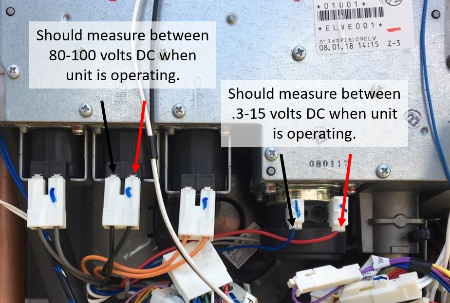
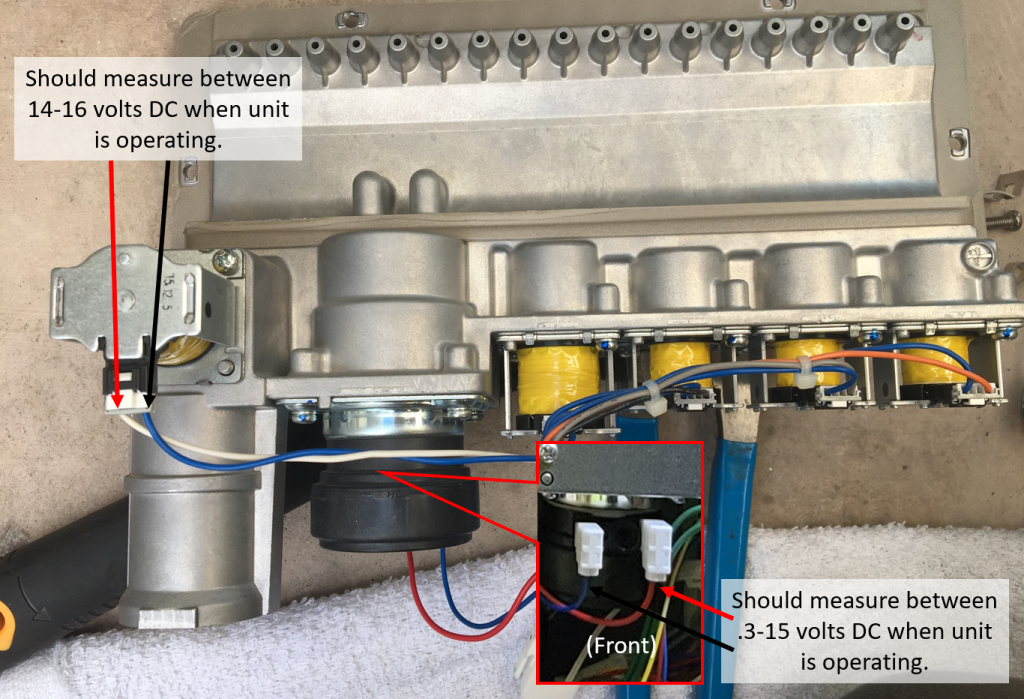
- If the board looks OK visually and the other steps have been checked and confirmed OK, test the voltage going to the gas valve or solenoids with a multimeter.
Multimeter Testing (Large solenoids, such as N‐0751M):
- The main gas valve and solenoids should receive between 80‐100 volts DC when the heater is operating.
- The proportioning valve should receive between .3‐15 volts DC when operating.
*Note: If any of those are receiving significantly less than the above voltages, check wiring and replace circuit board.

Multimeter Testing (Small solenoids, such as NC1991):
- The main gas valve and solenoids should receive between 14‐16 volts DC when the heater is operating.
- The proportioning valve should receive between .3‐15 volts DC when operating.
*Note: If any of those are receiving significantly less than the above voltages replace the circuit board.

For further technical assistance call 866-766-7489 or use our Contractor Locator to find a local service representative.
