Just installed a CB180 or CB199? Get some tips here.
This guide is to help get your CB180 or CB199 wired and started up correctly.
If you don’t have the physical copy of the installation and owners guide, please download them from our Support Site to understand the full scope of properly installing and setting up a CB180 or CB199.
Has the domestic and heating pipe system been flushed?
If not then you should flush out both the domestic and heating pipes.
Are both the domestic and heating side of the system hooked up?
If the domestic side is NOT, that is ok it doesn’t need to be.
If the heating side is NOT, at minimum the following hardware below needs to be installed:
- Auto feeder (Pg. 30-31)
- Expansion tank (Pg. 27). The expansion tank should be mounted on a loop between the supply and return.
- Pressure Relief Valve (Pg. 29)
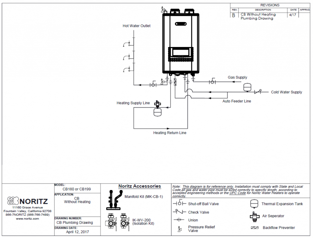
Figure 1: CB Without Heating Plumbing Diagram.
DO NOT hook the TT connection for the heating circuit (CN15) up or the ODTS if the boiler side isn’t completely installed.
DO NOT install expansion tank to PRV connection, near the return connection.
Has the CB heating side been filled with water and purged of air?
If YES, please follow the instructions on page 40.
If NO, then manually fill the system and purge it of air before turning on the CB.
Notes: EC54 is not a unit failure, it indicates that the CB is trying to fill the heating side with water. The CB unit will not purge the other heating zones of air, that needs to be done manually.
Is the unit installed at a high elevation?
If YES, go into “Installer Mode” and adjust 7:EL to the proper elevation range. The default setting is 0-1999 feet (0-2). Other ranges available are, 2000-4999 feet (2-5), 5000-7999 feet (5-8), 8000-10000 (8-10).
If you are unable to set the elevation check the PCB version in “User Mode” K:Pr Pcb. If the PCB version is 00.01 the circuit board will need to be updated, if it is 00.02 or later the unit will have the elevation settings available. Please contact Noritz Technical Support at 866-766-7489 for more assistance.
What type of radiant heating system is the CB hooked up too? This needs to be known for setting the temperature.
Baseboard, Cast Iron Base Board, Air Handler, Radiator, High or Low Mass Radiant in Floor. (Pg. 43)
High mass indicates the tubing is run through concrete and low mass would indicate it is stapled up to the floor joists or on top of the floor with aluminum plates (for example: Quik-Trac from Uponor).
FOR HEATING SYSTEMS AT OR BELOW 140: Go to “User Mode” and select K:Pr to check the PCB and PNL (front panel) versions. Replace the front panel and PCB if the front panel is version 00.01 and or the PCB is version 00.01 or 00.02. The unit needs to have the front panel version 00.02 and PCB version 00.03 in this type of application.
Are you using PVC, CPVC or PP for your exhaust venting?
If the heating application has return temps above 149°F or supply temps above 160°F verify CPVC or PP is installed and change 6: VT to CPVC. (Pg. 15, 49)
DO NOT change 6:VT to CPVC unless the proper venting is installed.
Do you have a primary-secondary loop? (Pg. 36-38)
If you have multiple zones you need to have a primary secondary loop.
Do you have an external pump on the heating side? (Pg. 35-36)
Are you drawing power from the CB or from and external source? If drawing power from the CB verify power draw of the pump max: 125V/2A and turn 10:EP on. (Pg. 34, 51) The top leg labeled 1 is neutral the bottom leg labeled 2 is hot.
Is a low water cut off (LWCO) being installed on the CB? (Pg. 28).
If yes, then make sure it is wired to CN17 for power and CN22 for the LWCO sensor.
Is this a retrofit install and how many wires are there available for the CB PCB wiring?
For all heating types including air handler, if there are only 2 wires available and you cannot add additional wires for wiring to the CB PCB then follow steps 1-2 and see Figure 1 below.
- CN15 (T-T connection) is hooked up to the thermostats (RH and W) or zone controller.
- Even for air handler heating system CN20 is not wired to anything.
Note: Since the air handler will always be on until thermostat is satisfied, you will experience cold air when CB is supplying DHW, turned off and auto filling water. Installer Mode “8:AH” remains off.
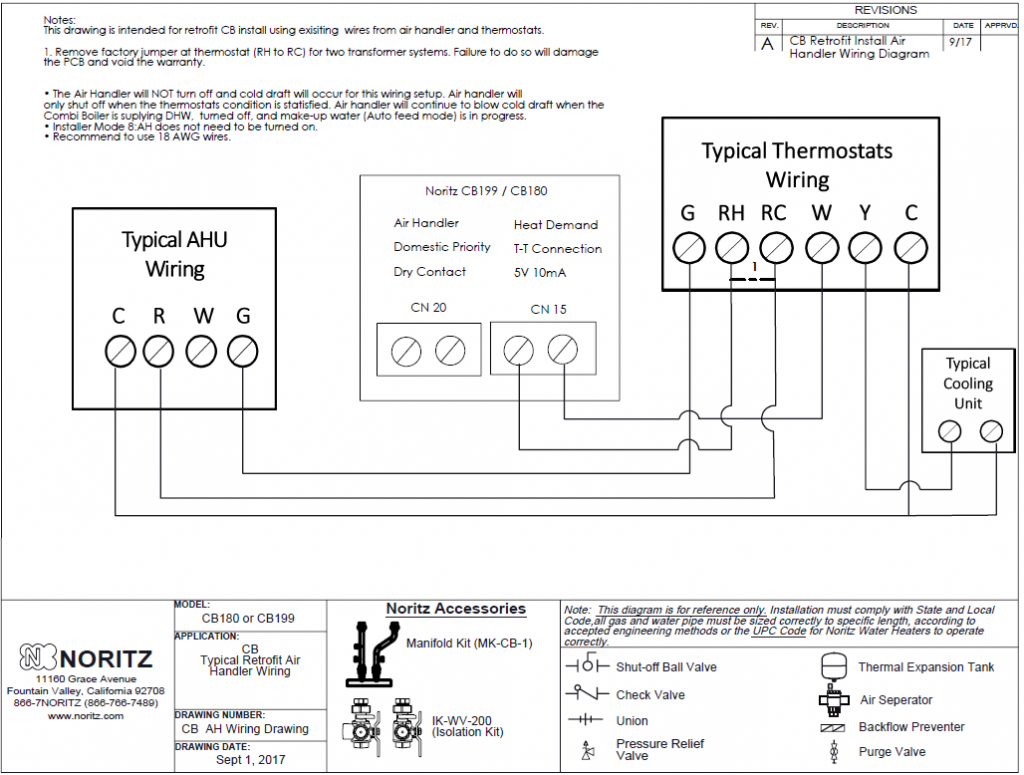
Figure 2: CB Retrofit Install Air Handler Wiring Diagram
Note: Remove factory jumper at thermostat (RH to RC) for two transformer systems. Failure to do so will damage the PCB and may not be covered under warranty.
Is this a new install? There must be at least 4 wires available for the CB PCB. See steps 1-2 and figure 3 below.
- CN20 is hooked up to the air handler (G connection and thermostat G connection) and in ‘Installer Mode’ 8:AH is turned on. (Pg. 34, 39, 50)
- CN15 (T-T connection) is hooked up to the thermostats (RH and W).
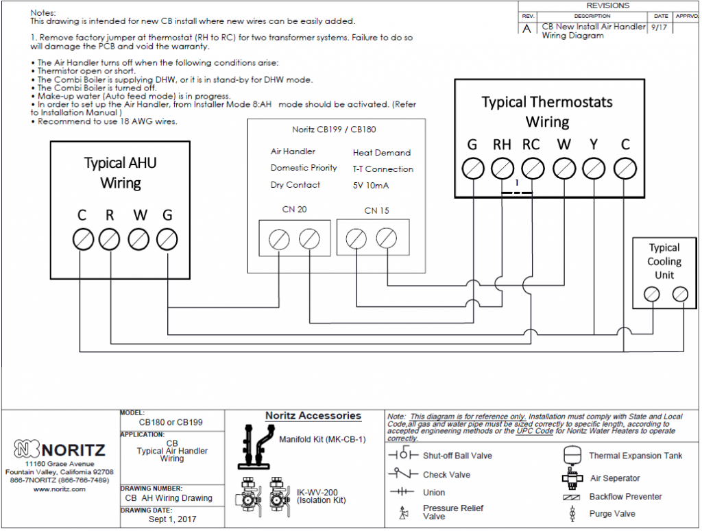
Figure 3: CB New Install Air Handler Wiring Diagram
Note: Remove factory jumper at thermostat (RH to RC) for two transformer systems. Failure to do so will damage the PCB and may not be covered under warranty.
Are you using a zone controller, relay or thermostat to create your heat demand? (Pg. 34)
If a thermostat is hooked up to CN15 make sure it is not drawing power from the CN15 connection to power the remote.
If a zone controller or relay is being used verify that its end switch or heat demand (TT Connection) is hooked up to CN15.
Is the Outdoor Temperature Sensor going (ODTS) to be used?
If YES, “2:TR” must be turned on in “Installer Mode” (Pg. 42)
Once 2:TR is on then you will have access to 3:TY, and 4:Od. They should be set according to the installation manual. (Pg.41-44, 46-48)
*Verify that the ODTS is installed outside and not in direct sunlight, preferably on a North or Northeast facing wall under an eve. (Pg. 46)
*If the ODTS icon is continuously blinking, verify the ODTS wires are firmly connected on both ends and that 2:TR is on.
If NO, you need to set the high and low supply temps in ‘Installer Mode” 1:HT. Then set the boiler temperature for the unit. (Pg. 21 Owners Guide)
Note: The ODTS icon will blink constantly when it is not hooked up even with 2:TR OFF. This does not indicate a problem.
Review ‘Installer Mode’ and make sure the setup is in accordance with the type of system you have (Pg. 47-51)
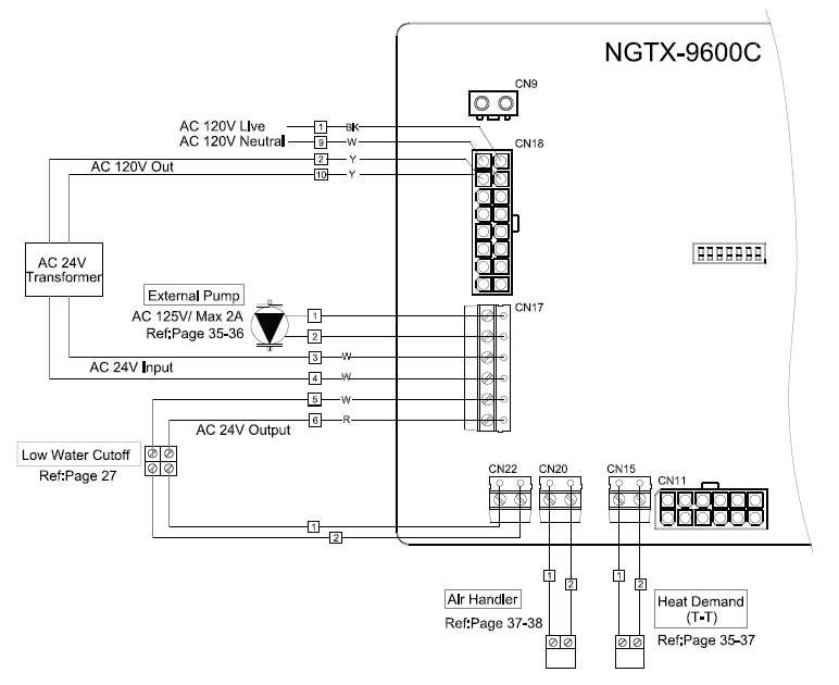
Figure 4: Page 34 of CB Installation Manual